

One structure, different representations
A coordinated BIM model describes physical components for documentation, quantities, fabrication, and interface review. A structural analysis model idealizes behavior using nodes, members, surfaces, restraints, releases, and loads. These representations are related but not identical.
A beam's physical offsets, slab openings, and connection plates may be modeled for construction clarity while the analysis model uses a simplified centerline or surface. Copying geometry without understanding assumptions can make the analytical model less reliable, not more.
State the analytical question
Before connecting models, define what analysis is being performed and which assumptions govern it. A global stability model, local slab analysis, connection design, and temporary-stage check may require different idealizations.
For a hypothetical transfer level, the analysis model might need a specific diaphragm assumption and support condition that cannot be inferred from the visible BIM geometry. Keep the responsible engineer's basis of design and calculation records authoritative. The BIM relationship should help trace changes, not replace analysis judgment.
Map physical members to analytical elements
Establish how a physical column, beam, or wall maps to its analytical counterpart. The mapping may use stable identifiers, shared parameters, or a controlled exchange table. Decide how split members, merged analytical elements, eccentricities, and offsets are represented. If one physical object maps to several analytical elements, record that relationship.
A simple one-to-one assumption can fail around transfer systems, irregular framing, or staged construction.
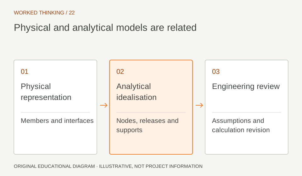
Read diagram notes
- Physical representation
- Members and interfaces
- Analytical idealisation
- Nodes, releases and supports
- Engineering review
- Assumptions and calculation revision
Validate connectivity and restraints
A model can look connected while its analytical nodes are disconnected, or appear discontinuous while rigid links or constraints correctly connect it. Inspect analytical connectivity, releases, supports, and load paths in the analysis environment. Compare key locations with the physical model and engineering sketches.
For example, verify that a transfer beam's support and continuity assumptions match the intended structural system. The check should be performed by a competent structural engineer; visual coincidence is not proof of structural behavior.
Manage loads and combinations explicitly
Loads, combinations, and construction stages may live outside the physical BIM model or be represented only as references. Define the source of each load, units, application area, and combination basis. If the BIM model carries descriptive load data, clarify whether it is authoritative or informational. Never infer a safe design from model properties alone.
The approved calculations and applicable design criteria remain the evidence for capacity and serviceability.
Propagate geometry changes selectively
A moved grid, revised opening, or changed member size may affect both representations, but not always in the same way. Establish change triggers that flag analytical review and identify who decides whether recalculation is required. Compare revised physical and analytical models around affected regions.
An automated update may move a node but fail to preserve a release or support condition. The engineer must verify the meaning of the updated model before relying on new results.
Keep results tied to the analyzed revision
Analysis results should identify the model version, load cases, combinations, assumptions, and software settings that generated them. If geometry changes afterward, do not let old results appear current without review. Link calculation documents or result sets to the relevant model revision in the controlled environment.
A color-coded utilization view is useful for communication, but without context it can mislead recipients about design status.
Use automation as a traceability aid
Scripts and visual programming can help map objects, update analytical representations, compare revisions, or flag exceptions. They should expose transformations and assumptions rather than conceal them. Start with a small test structure and known cases, then independently inspect outputs. Document what the automation cannot detect, such as an inappropriate restraint assumption or incomplete load path.
Automation can reduce repetitive transfer work while preserving the engineer's responsibility for analysis and approval. A change log can identify what prompted each analytical update: revised geometry, changed support assumptions, new loading, or a correction to connectivity. Reference the resulting calculation revision and review status.
This is especially important when the physical model continues to develop while analysis is underway. It helps reviewers distinguish a synchronized model from one that merely looks similar, while keeping the responsible engineer in control of the technical conclusion.
Keep the comparison focused on the changed region and connected load path; unrelated model differences can otherwise obscure the engineering review.