

Start with the decision
An early-stage family is useful when it helps a team compare spatial arrangements quickly. Imagine a timber floor zone where designers are testing bay widths and floor-to-floor heights. A parametric assembly can make repeated layout adjustments easier to communicate than isolated placeholder lines. Its value is speed and consistency during option development, not engineering certainty. Before using one, define the decision it supports: comparing spans, checking a plant-room envelope or illustrating a typical bay. Identify who will interpret the result and what information must accompany it. A family suited to visual planning may be unsuitable for quantities, connection design or construction documentation.
Inspect what the container holds
A container family may include nested structural framing or column elements. If components are shared and schedulable, they may appear as individual project elements and feed schedules. That differs from one generic shape that only resembles an assembly. Inspect the family in a clean test project: select members, review categories and types, and check whether expected components appear in schedules. Do not assume that a visible beam-like object is a structural framing object. Category and family behavior affect documentation and exchange. If the assembly contains nested shared components, verify identity and schedule behavior. Document the inclusion convention so a reviewer understands what a schedule counts.
Make parameter changes observable
Adjust one input at a time: length, width, storey height or spacing. After each change, inspect geometry and component count. Look for gaps, overlaps, unsupported extensions or members that remain unchanged unexpectedly. A dimension shown in properties is an input, not proof that the family handles every combination. For a hypothetical 6-by-8-metre bay, test the nominal case and the smallest and largest expected options. Check plan and section, not only 3D. If values are rounded or constrained, make that visible. Do not stretch a family beyond its tested range and present the result as a validated structural arrangement.
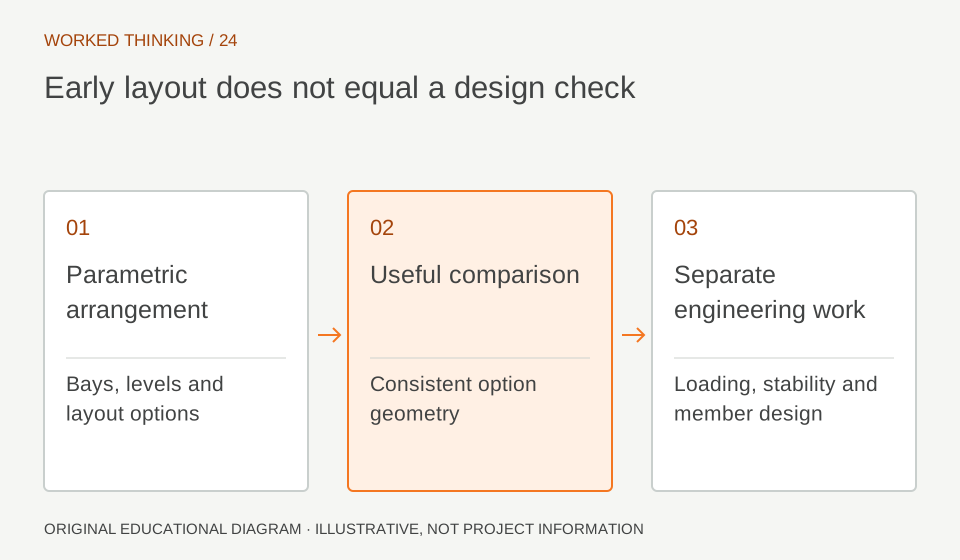
Read diagram notes
- Parametric arrangement
- Bays, levels and layout options
- Useful comparison
- Consistent option geometry
- Separate engineering work
- Loading, stability and member design
Separate geometry from engineering
An early system family can represent realistic components while omitting loads, support assumptions, material grades, stability checks and connection design. Use a model note or view label to identify it as an early representation. Do not infer capacity or suitability from detailed members. The engineer of record remains responsible for analysis and approved sizing. When design advances, replace or verify placeholders against coordinated design information. Establish a handoff trigger: once layout is accepted, confirm spans, member series, support conditions and openings. This prevents a visual model from becoming an unexamined source for fabrication or procurement.
Use schedules diagnostically
A live schedule can reveal whether nested components update when an assembly changes. Build a test schedule with category, family and type, level, and a useful identifier. Apply explicit filters based on the family’s inclusion convention, then compare the schedule against manual selection in a known bay. A schedule is a model check, not self-validating output. If inclusion relies on a comments field or sentinel value, inspect that value on representative components. A missing value can omit an item. Keep an audit schedule that exposes the filtering field during development; hide it from issued sheets only after the convention has been verified.
Manage repetition and marks
Repeated assemblies create a risk that copied instances look distinct while carrying ambiguous marks. Decide whether identifiers belong to the assembly, nested members or both. A module mark may identify a bay-level system, while member marks remain distinct where design or documentation requires it. Do not assume globally unique identifiers unless configured and tested. Place two instances and compare nested elements. Confirm how marks, types and schedule rows behave after duplication. If the model is divided across files, check that receivers can identify each element unambiguously. Prefer a simple, documented convention over a clever scheme only one author understands.
Review, exchange and retire
At each issue, state the phase and intended use. Include a limitation note and identify placeholders. If exchanging IFC or another format, test a sample and verify categories, names and identifiers in the receiving model or viewer. Do not infer interoperability from a successful export dialog. When moving from option study into developed design, decide whether to retain, replace or decompose the assembly. Record its version and the design information that supersedes it. Controlled retirement prevents obsolete geometry from persisting beside approved members and confusing quantity or review workflows.