
Start with nominal geometry
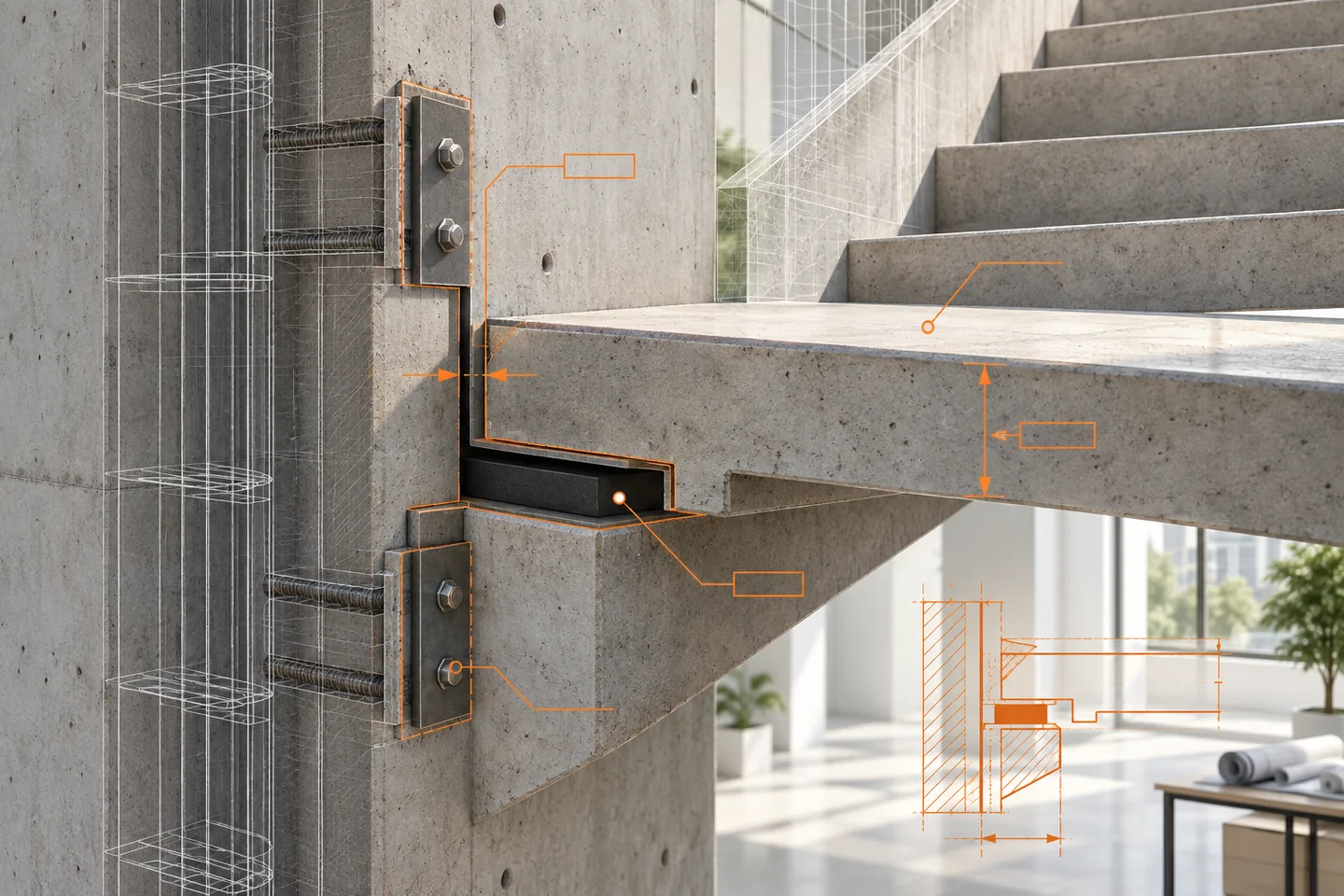
Precast coordination starts with nominal geometry, but erection success depends on controlled allowances and the authority that defines them. A stair landing at a cast-in-place core should identify its support line, joint, bearing pad and connection references before anyone treats the visible gap as a confirmed tolerance.
Show the allowance separately
Model the nominal unit and the receiving structure as separate objects. If an allowance envelope is shown, label it as a coordination zone rather than adding it to the concrete geometry. This prevents schedules and clash tests from treating a construction allowance as a fabricated dimension.
Follow the erection sequence
Review the path from delivery to final support. Crane access, temporary restraint, sequence and adjacent trades can affect whether an interface is practical. These are coordination prompts; the approved erection method and temporary conditions must come from the responsible parties.
Read diagram notes
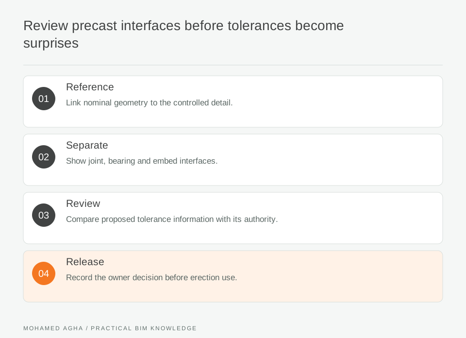
- Reference
- Link nominal geometry to the controlled detail.
- Separate
- Show joint, bearing and embed interfaces.
- Review
- Compare proposed tolerance information with its authority.
- Release
- Record the owner decision before erection use.
Track embedded items by reference
Embeds, sleeves and cast-in plates need a controlled reference to the detail or shop package. A generic plate in the model is not enough. Check that identifiers, level and orientation match the latest package and that any site survey dependency is clearly stated.
Check a landing against surveyed reality
Take a stair landing that meets an in-situ wall. The nominal model shows the intended seat, but a later survey reports a difference at the receiving surface. Retain the survey reference and compare the measured location with the governed unit and support details. Do not quietly stretch the precast family until the view looks correct. Ask the responsible precast and structural parties to decide whether the discrepancy affects the unit, support, installation allowance or another interface. Link their response to the specific landing identifier and update the affected release status. Recheck the adjacent stair flight, finish build-up and delivery sequence against that response. A useful close-out record explains how the discrepancy was handled and which information now governs; it does not substitute a model adjustment for an engineering instruction.
Review at the bearing line
Use a section through the actual bearing and joint. Check interface objects, finish build-ups, waterproofing and service routes. Record any clash against an agreed reference, not against an assumed millimetre value in the coordination model.
Keep tolerance authority outside the picture
Close only when the record identifies the governing detail, version and owner response. Do not claim a BIM view validates manufacturing, cumulative tolerance, lifting or erection safety.