

Start from a specific geometry problem
BIM Pure’s Revit 2027 roundup names 3D path rebar shape distribution but does not explain it in depth. Autodesk describes the workflow as free-form transverse reinforcement distributed along a three-dimensional path for complex, double-curved concrete elements. That suggests a bounded pilot: a hypothetical curved canopy rib or bridge web where a conventional planar view makes the changing host geometry difficult to inspect.
Treat the model as an authoring and documentation experiment. The feature does not determine reinforcement demand or prove that a proposed bar arrangement satisfies a design standard. Establish the intended bar, spacing, cover and detailing rules from an approved engineering source before opening the placement workflow.
Prepare a controlled host
Create a synthetic test element with a clear, continuous edge path and a cross-section that can be checked at several stations. Include one section near each end and one at a changing-curvature region. Save a baseline view and dimensions. Record the Revit build, rebar shape/type, layout rule, host geometry and any relevant cover references. Keep the sample separate from an active design model.
Start with a simple planar bar shape and a short path. This isolates path selection and distribution before complex testing. If host edges do not express the intended route, simplify the test or record that limitation.
Place the main bar before the path
Autodesk documents a two-stage operation: place the main bar using a suitable view and then select one or more continuous host edges to define the distribution path. In a section, the user can select a shape and placement method, define its dimensions, and proceed to path selection. The workflow can also be completed in a 3D view for a host that is visible and selectable.
For the pilot, inspect the main bar in section before distributing it. Confirm the plane, orientation and exact dimensions against the approved sketch or detail. Then select the intended continuous edge chain and verify the displayed path before finishing. A plausible-looking 3D result is not enough: trace the selected path through the host and confirm it corresponds to the intended reinforcement run.
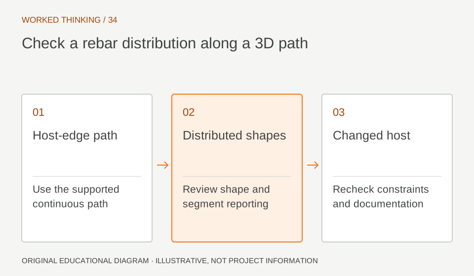
Read diagram notes
- Host-edge path
- Use the supported continuous path
- Distributed shapes
- Review shape and segment reporting
- Changed host
- Recheck constraints and documentation
Check what the set reports
After creation, inspect bars at multiple stations along the path, not only the first and last. Compare cross-sections with the host faces and the intended cover references. Check the set range, offsets and spacing representation, and verify whether dimensions remain appropriate where the host changes shape. Autodesk states that bars can be constrained to host edges so segments or ends adjust as host dimensions change; test the specific constraint behavior rather than assuming every segment follows the desired face.
Review schedules and tags as well as geometry. Autodesk’s documentation distinguishes shape matching from unsupported sketches: when Workshop Instructions is set to Bend, supported geometry can match a rebar shape and report segment lengths; unsupported sketches can still be modeled but report total length only. Decide whether the pilot’s fabrication output needs shape and segment information, and verify the result in the actual schedule configuration.
Change the host deliberately
In a copy, change one host dimension or edge condition that should affect the path-based set. Observe which bars and dimensions update, then compare them to the intended constraints. Repeat with a modest path-range adjustment. Capture any member that remains fixed, changes unexpectedly or loses the expected shape representation. This is a test of model association and documentation behavior, not an automated design validation.
If the host change is a real design revision, the responsible engineer must determine the required reinforcement response. The model’s adaptation can help expose coordination work, but it cannot decide whether bar size, spacing, anchorage, lap, congestion or constructability remain acceptable.
Inspect drawings and exchange
Create a section through the most demanding curvature and a 3D view that communicates the full distribution. Check visibility, bar identity, dimensions and legibility at the intended sheet scale. Review whether tags and schedules distinguish this set from adjacent reinforcement. If the project exchanges reinforcement through IFC, fabrication software or another downstream process, export only a controlled sample and inspect it in the receiving tool with the recipient’s agreed checks.
Record losses explicitly. A successful Revit display does not demonstrate that downstream tools preserve geometry, marks or fabrication data. If exchange is unverified, limit the conclusion to native Revit.
Write a narrow decision
The outcome should name the tested host type, supported path conditions, bar shapes, schedules, views and known limitations. Ask another detailer to repeat the operation from the written steps. Compare their result with the baseline sections and schedule, not just their impression of speed. A repeatable test is stronger evidence for adoption than a single successful placement.
Adopt the workflow only for the geometry and outputs actually checked. Defer it where path continuity, shape matching, drawing clarity or exchange remain unresolved. Design approval, calculations and constructability review remain in engineering processes; the feature supplies a modeling method, not those approvals.