

Begin with the purpose
A clash report is a list of geometric intersections, not a design decision. Before checking, define what the structural model is being coordinated for: spatial reservation, design development, reinforcement, steel fabrication, or construction sequencing. Each purpose needs different detail and comparisons. Early coordination may focus on primary framing, columns, walls, transfer elements, major openings, and main service routes. Fine details can create noise before the design is stable. State model revision, zones, categories, tolerance, and reviewers so another person can repeat the check. Link every review cycle to a decision or delivery that benefits from it.
Connect physical and analytical intent
The physical model describes shape and position for drawings and spatial coordination. The analytical representation simplifies structure for engineering analysis, with members, panels, nodes, materials, loads, and boundary assumptions as applicable. Autodesk documents this analytical representation and its relationship to physical elements, while Revit-version workflows have evolved. A beam can look aligned in 3D while its analytical endpoints do not connect as intended. Before sharing analysis information, inspect continuity, connectivity, supports, releases, offsets, and openings. These checks involve engineering assumptions and cannot be replaced by a visual clash run. Record which model is authoritative for geometry and which values have been reviewed for analysis.
Coordinate interfaces with consequences
Build a small test matrix around important interfaces: column versus façade zone, transfer beam versus duct corridor, brace versus door clearance, slab edge versus riser, and foundation top versus site services. Select relevant categories or zones and inspect each result in context. Autodesk’s Interference Check finds intersections within a model or between host and linked Revit models, but its category and element coverage has limits. Autodesk documentation directs users to Navisworks for detailed steel and MEP fabrication parts. Select a tool that covers the objects included in the exchange and record excluded categories. A test matrix makes the limits visible and helps the team avoid interpreting a partial check as complete.
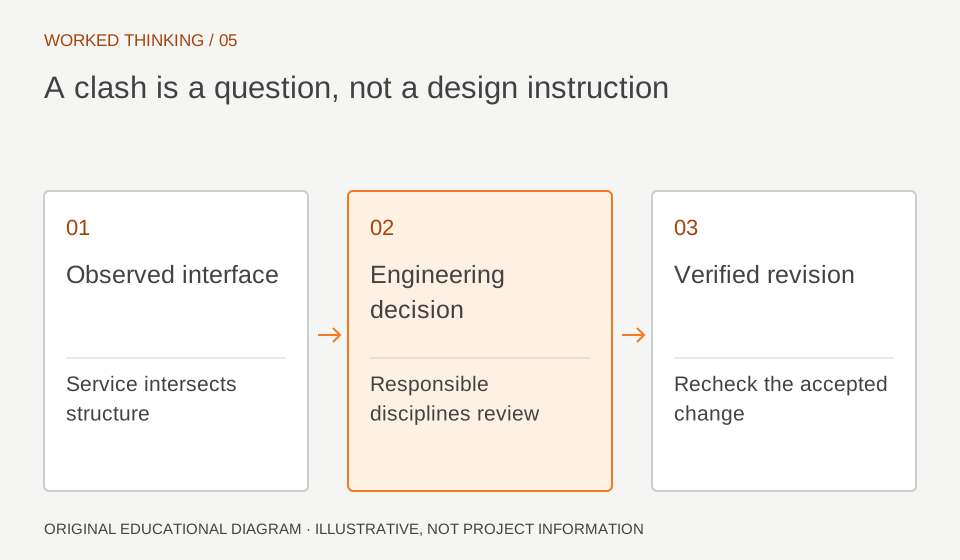
Read diagram notes
- Observed interface
- Service intersects structure
- Engineering decision
- Responsible disciplines review
- Verified revision
- Recheck the accepted change
Coordinate model versions and package boundaries
A clash matrix is useful only when the model set represents a known coordination moment. BIM Pure guide distinguishes file and folder management, package transmission, federated models, and model coordination functions in its ACC discussion. Apply that separation to the structural cycle: identify which structural and services revisions are approved for review, transmit that set through the agreed process, and compare against those named versions. A new upload should trigger a deliberate decision to refresh the comparison, not silently replace the basis of open issues. This keeps issue records traceable when a beam or route changes between coordination rounds.
Classify before assigning
For each reported intersection, decide whether it is a real conflict, intentional connection, acceptable overlap, modeling artifact, or unresolved design decision. A duct through a beam may require rerouting, a designed opening, or a beam redesign; software cannot choose safely. Capture exact elements, level or zone, model revisions, view, and decision needed. Assign the issue to the discipline able to resolve the design, then identify who updates each affected model. This keeps the issue actionable and structural adequacy with the structural engineer. If the geometry is allowed, record why and who accepted it instead of merely marking the clash resolved.
Work through a transfer-beam example
Imagine a 600 mm deep transfer beam crossing a corridor with a 500 mm main duct. The raw clash is only the first observation. Check whether the duct route is fixed, whether an opening is planned, whether beam shear and reinforcement can accommodate it, and whether headroom still works. If the duct can shift, record the revised route and rerun the same comparison. If structure must change, route the decision through the engineer of record and update analytical and physical representations together. State acceptance in project language, such as preserving a specified clear duct envelope below the soffit. This frames the design choice and gives the team a clear verification target.
Close the loop
Run coordination at agreed milestones and after material design changes. Use stable identifiers so resolved items do not return as new noise. Preserve model versions, tests, results, accepted exceptions, and open actions for each cycle. A zero-clash result is not a quality certificate: it covers only selected categories, files, and rules. Pair it with drawing review, analytical review, and discipline sign-off appropriate to the package. The BIM manager controls process and evidence; the engineer remains accountable for design decisions. When the scope changes, update the test matrix so reviewers understand what the next result actually establishes. Keep the issue history short and readable so discipline leads can focus on decisions instead of reconstructing old discussion.